
Eta Research announces GaN wafers for laser diodes
Free-standing GaN wafers at sizes of 2 inches and 4 inches available in either Si-doped n-type or C-doped semi-insulating
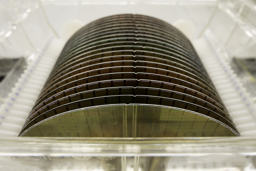
Eta Research has announced GaN wafers engineered for laser diode manufacturers. The company produces free-standing GaN wafers at sizes of 2 inches and 4 inches, with conductivity available in either Si-doped n-type or C-doped semi-insulating.
Eta has focused on a number of key parameters for the wafers including orientation flat alignment, dislocation density, offcut, lattice radius and offcut variation, frontside Ga-face polish, and backside N-face finish.
Orientation flat alignment
The wafer orientation flat must be closely aligned to the GaN m-plane since lasers may be manufactured by cleaving on the crystallographic plane. Eta has developed the process to achieve 0.0 ± 0.1 degrees alignment of the orientation flat to the crystallographic plane.
Dislocation density
Typical XRD rocking curve FWHM for both (002) and (102) are in the range of 40 to 50 arcsec. The dislocation density was measured by both CL and etch pit methods, and was found to be in the range of 5E5 to 9E5 /cm2.
Offcut
Eta’s standard offcut is 0.5 degrees toward the m-direction and 0.0 degrees toward the a-direction at the centre point of the wafer. The centre point offcut can be customized in the range of 0.2 degrees to 0.6 degrees
Lattice radius and offcut variation
The lattice radius specification is > 10 m, and typical values range from 20 m to 60 m with the shape as concave. The offcut variation can be calculated from the lattice radius. However, since there is a small concave wafer bow, the actual offcut variation is less than would be calculated from the lattice radius. The offcut was measure by XRD with x-ray reflection alignment to the real wafer surface. The offcut variation over a 4 inches wafer was measured as 0.06 degrees for the m-direction offcut and a-direction offcut. For example, the m-direction was 0.47 degrees on one edge and 0.53 degrees on the other edge over the entire 100 mm of the wafer.
Frontside Ga-face polish
The Ga-face is polished to an average roughness of 0.15 nm measured by a 10 µm x 10 µm AFM scan. The wafer is cleaned in a special process to remove any contamination from the polishing procedure. Removal of trace metal impurities from the surface was confirmed by TXRF.
Backside N-face finish
The backside finish is available in either polished or etched. The average roughness of the backside surface measured by 3D profiler over 239 µm x 318 µm is 1 nm for polished and 1 µm for etched.


